
Interesting, it is working for me in wayland and the drop down menus are fine but I’m using sway which is a totally different wayland implementation than what KDE is doing. I’m glad you found a workaround.
- 8 Posts
- 4 Comments
Joined 1 year ago
Cake day: June 11th, 2023
You are not logged in. If you use a Fediverse account that is able to follow users, you can follow this user.
Unfortunately I don’t know what is causing the exact issue you are having, however here are a few things I found when doing this myself that are “gotchas” (not immediately obvious).
-
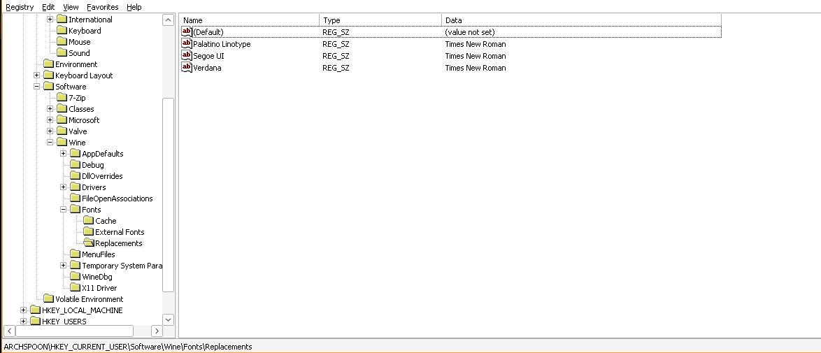
This is the reason your fonts are all Times New Roman. Go to that key using protontricks regedit and delete all the font replacements.
-
Anything you put in
$HOME/.steam/root/steamapps/common/assettocorsastays there, even if you uninstall the game. If you want to “start over” you have to uninstall the game and then delete the whole assettocorsa directory there, and the wine prefix in$HOME/.steam/root/steamapps/compatdata/244210 -
AC and content manager work without .net changes in the latest GE but you do need
corefontswhich you can install with protontricks. If you want to be extra sure you have the right .net you can install dotnet472 but I don’t believe this is necessary anymore as it will be installed automatically or is already installed. You may get a wine .net error the first time you launch the game but it’s only the first time. -
If you choose to use CSP you have to unzip the archive you get from either Patreon or acstuff.ru and manually copy the
dwrite.dllfile into$HOME/.steam/root/steamapps/common/assettocorsaon EVERY upgrade. The zip installer built into CM doesn’t do this correctly on Linux. It will cause rain not to work if you choose to use the Patreon version if you don’t do this manual step.
I think you should start over and make sure the assettocorsa directory is clean before re-installing the game. It could be missing fonts, but it’s hard to say. You can back it up somewhere if you have data in there you need.
-
I use FreeCAD and Assembly3 for everything and have for many years now. I sometimes use realthunder’s fork of FreeCAD but right now it’s quite a bit behind upstream and there are some cool new features in sketcher so I use upstream for those.
Some people get confused about workflow in FreeCAD because there are so many options and every youtube video has different opinions or tries to feature a particular workbench like curves or something. My opinion… Pretty much your workflow starting out should be to ignore everything else and use part design and sketches, it’s the simplest way:
-
enable autosave with a short interval, like 2min
-
Switch to part design workbench
-
create body
-
create sketches as the base of the features of your part attached to the xy, xz, yz planes, offset them to create a “wire frame” that resembles your project
a. Your sketches should be fully constrained
b. Your sketches should have as little geometry in them as possible, if you need more complex stuff make more sketches
c. Your sketches should have closed wires, you can’t pad something that doesn’t create a face.
-
use pad, pocket, revolution, loft, and hole operations on those sketches to form a 3d solid
-
if you need to create additional sketches which import geometry from the previous operations (using the external geometry tool), import SKETCH geometry from the previous ops, not edges of solids, whenever possible. Hide your solid, unhide your sketch, select that with the external geometry tool.
a. Use sketch on face sparingly.
-
Do fillets and chamfers last, if you need to change something, delete them and recreate them once you’ve made your changes.
To make multiple parts make multiple bodies with the same workflow as above.
Once you get pretty good at making static parts with constrained geometry, holes, threads (with the hole function), etc, which you can do with only the stuff above, then you can branch out into other workbenches like assemblies or curves, but all of those things build on the concepts above, so it’s easy to get overwhelmed if you try to do it all right from the start. Learning how to recover from a mistake is just part of CAD in general, though I admit that it’s a bit more effort to find what’s wrong in FC vs commercial platforms, but we aren’t here, on lemmy, in a linux community, to use commercial platforms.
AFAIK that’s pretty much the same workflow as F360 uses for single-solid parts though things have different names. pad=extrude for example.
It’s obviously far from perfect but in my opinion it’s the best solution that runs natively on Linux and is actually open source. Also assembly3 uses solvespace as it’s backend solver so if you make assemblies using that you are kindof using solvespace too.
Also, I hear/read a lot of complaining about instability but I’ve honestly never had a crash that wasn’t on an experimental branch like RT or the edge release of upstream. However step 0 above should help if you’re worried about that.
-
Disclaimer, I’m at a sortof “advanced hobbyist” level of cad. My understanding of the topological naming problem in general is that it exists in all cad because it is a sortof byproduct of how computers keep track of data about 3 dimensional objects. If you make a cube, all the sides need to have an identifier associated with them. If you put a hole in that cube, you now have more identifiers and have to decide what ordering makes sense. It sounds easy to work around with a cube but when models get really complex it’s not so easy, especially when you change something way back at the beginning which creates more or less faces in the middle of the list somewhere.
Freecad isn’t making the topological naming problem “go away”. They are creating (or rather merging, it’s been around a long time) an algorithm that makes a better guess at what the order should be, rather than sticking new faces in the list and reordering without any consideration of what happened after that face was created. This is, as far as I understand, also how other CAD packages do it, and you can still back yourself into a topological naming problem if you try hard enough (or don’t try at all I guess) in both freecad with the new changes applied, and in other CAD packages.
So “best practice” is to be smart about the attachment of your geometry thinking about how things might change in the future, rather than clicking the closest face whenever you need a sketch plane. In reality modern proprietary cad is so good at guessing and maintaining consistency that it doesn’t matter unless your model is horrendously complex and whoever made it didn’t pay any attention to laying out the base sketches in an organized way.
For example if you make a flange but you’re not quite sure about the thickness, base the sketch for say, the holes, on the parallel origin and offset it by the height of the pad or the length of the sketched geometry. Or use a spreadsheet or variableset for the value of both the thing that you define the thickness with, and the offset from the origin plane. That way if the value changes, nothing will break.
I made a test model but it isn’t something that shows up well in a single screenshot unfortunately. See the “Flange Thickness” and z offset parameters in the property view. I used that for the flange dimensions, and the hole sketch offset.